A heat pump system depends on proper thermostat wiring to deliver reliable heating and cooling throughout the year. Whether you are installing a new thermostat, replacing an old unit, or troubleshooting performance issues, understanding heat pump thermostat wiring is essential. Correct connections help maximize efficiency, improve comfort, and prevent unnecessary wear on HVAC equipment.
This guide acjakarta.com explains common heat pump thermostat wiring configurations and shares setup tips commonly recommended by HVAC professionals.
Understanding How Heat Pump Thermostats Work
Unlike conventional heating and cooling systems, heat pumps use the same equipment to provide both heating and cooling. The thermostat acts as the control center, sending signals to different components to switch between modes and regulate indoor temperatures.
Modern thermostats for heat pumps can control:
* Heating mode
* Cooling mode
* Fan operation
* Auxiliary heat
* Emergency heat
* Reversing valve operation
Because heat pump systems have additional functions compared to standard air conditioners, thermostat wiring is often more complex.
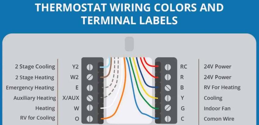
Common Heat Pump Thermostat Wire Colors
Although wire colors may vary, HVAC technicians generally follow standard conventions. Understanding these color codes can simplify installation and troubleshooting.
Red Wire (R)
The red wire provides 24-volt power from the transformer. Some systems have separate RC and RH terminals, while others use a single R connection.
Green Wire (G)
The green wire controls the indoor blower fan.
Yellow Wire (Y)
The yellow wire activates the compressor for heating and cooling operation.
White Wire (W or AUX)
This wire controls auxiliary heat. Auxiliary heat usually comes from electric resistance heating or another backup heat source.
Orange Wire (O)
The orange wire controls the reversing valve in many heat pump systems. It switches the system between heating and cooling modes.
Blue Wire (C)
The common wire supplies continuous power to smart thermostats and programmable models.
Brown or Black Wire (E)
This wire may be used for emergency heat operation.
Typical Heat Pump Thermostat Wiring Configuration
Most single-stage heat pump systems use the following terminal connections:
| Terminal | Function |
| -------- | --------------- |
| R | 24-volt power |
| C | Common wire |
| Y | Compressor |
| G | Indoor fan |
| O/B | Reversing valve |
| AUX/W2 | Auxiliary heat |
| E | Emergency heat |
More advanced systems may include additional terminals for:
* Two-stage compressors
* Variable-speed equipment
* Humidity control
* Wi-Fi communication
* Dual-fuel systems
Always refer to the equipment manufacturer's wiring diagram before making any connections.
Single-Stage vs. Multi-Stage Heat Pumps
Single-Stage Systems
Single-stage heat pumps operate at one capacity level. Wiring is relatively straightforward and usually requires fewer terminals.
Advantages include:
* Simpler installation
* Lower cost
* Easy thermostat compatibility
Two-Stage Systems
Two-stage systems offer improved comfort and energy efficiency.
Additional wiring may include:
* Y1 for first-stage compressor operation
* Y2 for second-stage operation
* W2 for auxiliary heat staging
Proper thermostat programming becomes especially important with multi-stage systems.
Setup Tips from HVAC Experts
Professional HVAC technicians emphasize several best practices when wiring heat pump thermostats.
Turn Off Power First
Always disconnect electrical power before working on any HVAC components.
This precaution helps:
* Prevent electrical shock
* Protect control boards
* Avoid accidental short circuits
Safety should always come first.
Label Existing Wires
Before removing an old thermostat, label each wire according to its terminal position.
Photographing the existing connections provides an extra reference during installation.
This simple step can prevent confusion and wiring mistakes later.
Use the Manufacturer's Wiring Diagram
Wire colors are helpful but should never be relied upon exclusively.
HVAC experts recommend using:
* Thermostat installation instructions
* Equipment wiring diagrams
* Terminal labels
The actual terminal designation matters more than the wire color itself.
Install a C-Wire for Smart Thermostats
Many smart thermostats require continuous power supplied by the common wire.
A C-wire helps support:
* Wi-Fi connectivity
* Touchscreen displays
* Remote temperature monitoring
* Software updates
Without a common wire, some smart thermostats may experience intermittent power problems.
Verify Reversing Valve Settings
Heat pumps use either O or B terminals to control the reversing valve.
Typically:
* O terminal energizes during cooling.
* B terminal energizes during heating.
Incorrect configuration can cause the system to produce heat when cooling is requested or vice versa.
HVAC professionals always confirm these settings during thermostat setup.
Program Auxiliary Heat Properly
Auxiliary heat is designed to provide additional heating during extremely cold weather.
Improper thermostat settings can cause auxiliary heat to run excessively, leading to:
* Higher utility bills
* Reduced efficiency
* Increased equipment wear
Modern thermostats offer settings that optimize when backup heat should activate.
Common Wiring Mistakes
Even experienced homeowners occasionally make mistakes during thermostat replacement.
Mixing Up O and B Connections
Incorrect reversing valve wiring is one of the most common problems in heat pump systems.
Symptoms may include:
* Cold air during heating mode
* Warm air during cooling mode
Correct terminal configuration usually resolves the issue.
Forgetting the Common Wire
Smart thermostats often require a dedicated C-wire.
Without it, users may experience:
* Blank screens
* Wi-Fi disconnections
* Battery drain
* Thermostat rebooting
Incorrect Auxiliary Heat Wiring
Miswiring auxiliary heat can cause:
* Constant backup heat operation
* Poor efficiency
* Excessive energy consumption
Professional installation helps ensure proper staging and operation.
Ignoring Thermostat Programming
Wiring alone does not guarantee proper operation.
After installation, HVAC technicians recommend verifying:
* System type selection
* Heat pump mode
* Number of heating stages
* Auxiliary heat configuration
* Reversing valve settings
Programming errors can mimic wiring problems.
When to Call an HVAC Professional
Although replacing a thermostat may seem simple, some systems are more complex.
Professional assistance is recommended for:
* Variable-speed heat pumps
* Two-stage or multi-stage equipment
* Dual-fuel systems
* Communicating thermostats
* Unidentified wiring
* Troubleshooting persistent problems
Certified HVAC technicians have the tools and expertise needed to ensure safe and reliable operation.
Final Thoughts
Understanding heat pump thermostat wiring is essential for maintaining comfort and efficiency. Proper wiring, accurate thermostat programming, and attention to manufacturer specifications all contribute to dependable system performance.
By following proven setup practices and avoiding common mistakes, homeowners can enjoy efficient heating and cooling throughout the year. When dealing with advanced systems or uncertain wiring configurations, consulting an HVAC professional remains the best way to protect your investment and ensure your heat pump operates at peak performance.